
Cleaning Plate and Frame Heat Exchangers
Posted in Engineering
Central Plants may utilize plate and frame heat exchangers for “free cooling” or other types of heat transfer. Maintenance of your plate and frame heat exchanger should be part of your scheduled service program.
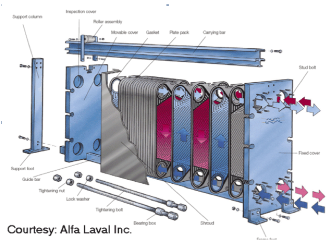
The plate exchanger, shown below, consists of corrugated plates assembled into a frame. The hot fluid flows in one direction in alternating channels while the cold fluid flows in true countercurrent flow in the opposite alternating channels. The fluids are directed into their proper channels either by a rubber gasket or a weld, depending on the type of exchanger chosen.
Typical plate thicknesses range from 0.40 mm to 0.60 mm and passage channel openings can range from 1.5 mm up to 11.0 mm, depending on the application and required design pressure (the larger the opening, the lower the design pressure available). These small passages also restrict the size of solids that can be successfully passed through the exchanger.
Solids can enter the plate and frame heat exchanger from a cooling tower or from debris from the closed loop. The solids then will restrict the flow through the plate and reduce the temperature heat exchange.
When do you need to perform maintenance on your heat exchanger? The best indication of problems is by logging of the temperature and pressures entering and leaving the heat exchanger. As the pressure differential starts to increase or the temperature difference starts to decrease, cleaning should be scheduled.
If your plant has two heat exchangers piped in parallel, note the temperatures and pressures of the two heat exchangers. Differences indicate a need for cleaning. Normally, the first in line will require more frequent cleaning.
By simply removing the compression bolts and sliding away the moveable end frame, you can visually inspect every square inch of each plate. Most plates are bounded on the perimeter by a single onepiece gasket. The “porthole” locations have individual gaskets.
The gaskets are either locked in or held in place with adhesive. Care must be exercised when removing the gaskets. Consult your operations manual on the cleaning process of the gaskets if you plan on reusing the gaskets.
Plates may be cleaned while still hanging in the unit or when removed. A highpressure washer may be used as long as the water stream does not undercut the gaskets.
Reassembly of the plates and tightening of the bolts is critical to allow for the proper alignment and sealing of the plates. Consult your operations manual for the proper sequence.
An option for cleaning is to back flush the plates. Some piping arrangements allow for the flow of water to reverse, flushing the plates.
Another option is to flush the heat exchanger through taps in the main pipes. With the isolation valves closed, a small pump can flush the plates from a bottom to top flow. Care must be taken if using any type of chemical cleaner or detergent. Again, consult the operations manual.
The unit also lends itself to easy and economical clean-in-place (CIP) procedures because the amount of retained liquid is very low.


 Previous STORY